As complex as the Internal Combustion Engine (ICE) is, it really doesn’t need much to make it work: For the spark ignition engine it needs fuel, an ignition source and compression – all timed to work in unison. For the compression ignition engine it doesn’t even need a spark.
The trick in getting these engines to work efficiently is to make sure that the fuel and spark arrive at the right time so that the ignited compressed-fuel mixture can best exert pressure on the piston.
Until the advent of fuel injection and engine management electronics, this timing was simply controlled by the ignition distributor and the vacuum in the inlet manifold that drew air and fuel into the combustion chamber at the right time.
In the modern electronically controlled and managed engine, the crankshaft position sensor – also known as the crankshaft angle, or even crankshaft speed sensor – informs the electronic control unit (ECU) of the precise position of the crankshaft, usually relative to top dead center (TDC) of the number one cylinder, for fuel and ignition to be delivered on time.
While modern ICEs make use of a myriad of sensors to optimize performance, there are only a handful that, when they fail, will render the car inoperable. One of these is the crankshaft angle sensor, often abbreviated to CKP in technical jargon.
Locating the Crank Angle Sensor
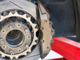
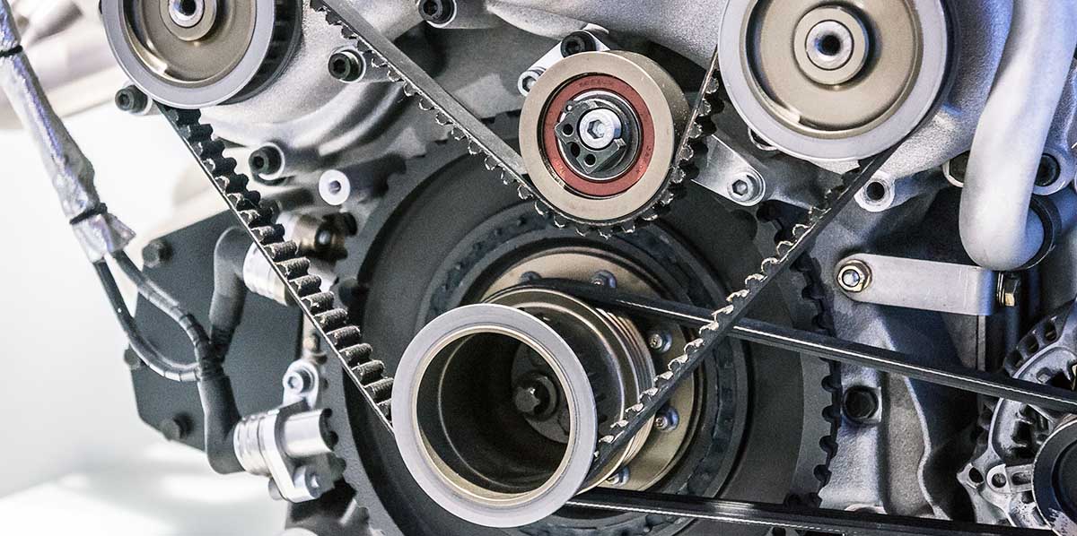
As the sensor records the angular displacement, and sometimes rotational speed of the crankshaft, it will always be found in close proximity to either the crankshaft pulley or harmonic balancer on the front of the engine; or the flywheel in the transmission bell housing at the rear.
With most CKPs relying on the disruption of a magnetic field to generate the signal, the sensor is positioned so that the teeth on a ring attached to the crankshaft pass close to the sensor tip, with the air gap typically set to around 1.25 mm, or .050 in.
How Does the Crankshaft Position Sensor Work?
To track the position of the crankshaft, a toothed wheel, also known as a reluctor ring, attached to the rotating crankshaft disrupts a magnetic field as it passes the sensor. The on-off signals thus generated allows the ECU to determine both the position and, if desired, the rotational speed of the crankshaft.
It is quite common for the reluctor wheel to have six slots, set 60 degrees apart – with a seventh, spaced 10 degrees from one of the others, used to generate an extra synchronization pulse every revolution. For fine measurement in special applications, the reluctor ring could have up to 360 teeth, with each one representing one degree of crankshaft rotation.
While the reluctor ring generates the pulses, the crank angle sensor is responsible for transmitting the signals to the engine ECU for processing.
The two sensor designs most commonly used are:
- The magnetic sensor, characterized by its two fly-leads, uses a pick-up coil to generate an AC-voltage analog signal, based on fluctuation of a magnetic field. As the crankshaft speed increases, so to does the number of oscillations which increases the voltage output to the ECU. This is translated into crankshaft speed and position.
- A Hall-effect crankshaft position sensor produces a digital square-wave signal and can be identified by its 3-lead harness consisting of a reference voltage, earth and signal wire.
What is more, depending on the functional requirements, these sensors can be doubled up or even used together with other devices to optimize engine performance:
- In what GM describes as a “combination sensor”, the crank position sensor consists of a pair of Hall-effect sensors, generating two individual signals. The pulses for these signals are independently produced by two reluctor rings fitted to the back of the harmonic balancer: One ring, with three notches, emits three crank position pulses every revolution, while the other ring with a single notch generates a single synchronization signal.
- In an effort to improve starting, engineers have on occasion also added a camshaft angle sensor, mounted over the timing gear, to a pair of Hall-sensors that pick up individual signals from the crank pulley. In this arrangement one sensor typically generates 3 pulses per revolution with the other producing 18, which together with the camshaft position information enables the ECU to more accurately deliver fuel and spark.
Similar in design to the CKP, the camshaft position sensor sends information to the ECU about the position of the camshaft relative to the crankshaft rotation which is used to determine which piston in the engine’s firing sequence is at TDC.
The camshaft sensor is commonly found on engines with distributorless ignition and sequential fuel injection systems and, together with the crank angle sensor, plays an important role in synchronizing the sequential fuel injection to the correct firing order.
See also: The Best Fuel Injector Cleaners
With the crankshaft position sensor responsible for relaying critical information about the crankshaft’s position and speed, an outright failure will result in an engine that doesn’t run – but so will a myriad of other problems.
So, what are the most common problems that lead to the CKP’s failure and how would a driver know that the sensor has a problem?
Most Common Problems With Crankshaft Position Sensors
While there may be a number of reasons why a CKP would fail, problems most often manifest themselves in engine timing issues, which can make an accurate diagnosis very difficult.
To simplify the fault-finding process it is always helpful to begin with the common problems assosciated with the sensor, and their related symptoms.
Besides an obvious electro-mechanical failure of the sensor or a wiring harness problem, there are a few other issues that afflict the crankshaft position sensor’s ability to function correctly.
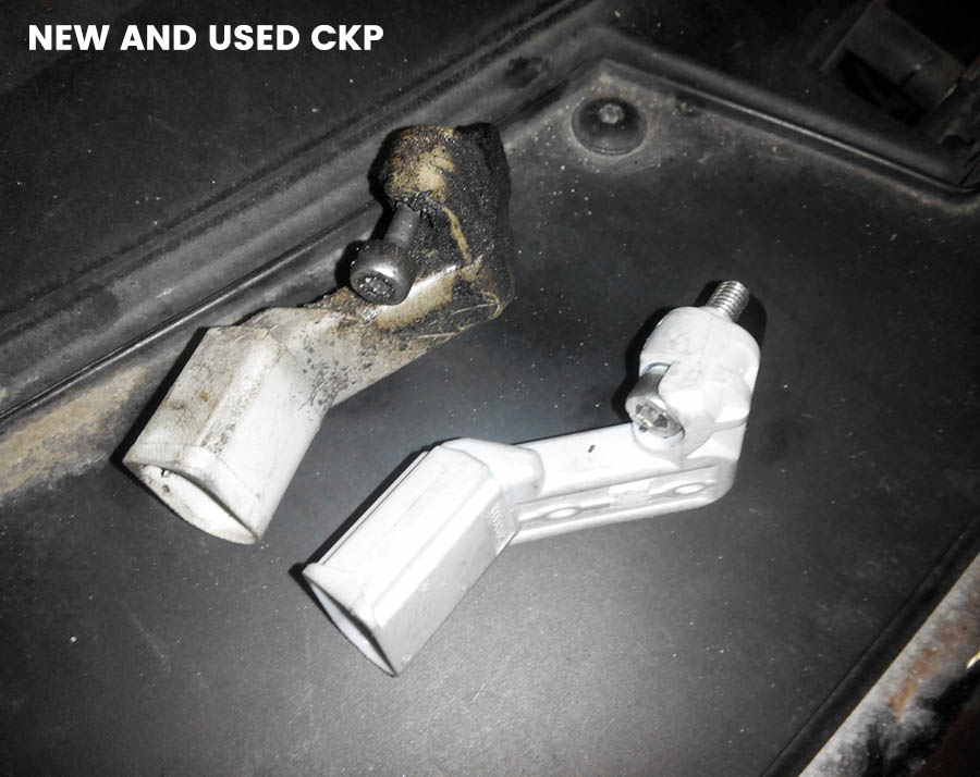
Top of the list of common problems is an accumulation of dirt and oil on the sensor tip: With sensors that are mounted at the front of the engine, exposed to road grime and any oil from an engine oil-leak, it is quite common for a buildup of dirt over time to disrupt the sensor’s ability to pick up the pulse generated by the reluctor ring.
See also: 15 Best Synthetic Engine Oils
Another problem that is commonly found on CKPs mounted near the crank pulley is a misalignment of the sensor’s mounting bracket.
This is often as a result of:
- Misalignment of the bracket after a repair or part replacement.
- Accidental damage which forces the bracket out of alignment.
- Inadequate tightening of the mounting bolts which allows the sensor to move out of alignment
Even though there are relatively few things that can go wrong with the sensor, identifying a failure is not always easy.
Crankshaft Position Sensor Malfunction Signals
The most obvious signs of an outright failure of the sensor or its related circuitry is an engine that simply won’t start: With a lack of signal from the sensor there will be no spark or fuel injection, so the engine will not run.
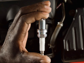
See also: The Best Spark Plugs for Car’s Engine
Other common signs and symptoms of a failed or problematic crankshaft sensor include:
- Engine check light does not extinguish – A failing or failed crankshaft position sensor could cause the check lamp in the instrument panel to remain on.
- Difficult starting or engine stalling – Unlike a failed CKP sensor, that will prevent the car from starting, a problematic crank angle sensor could lead to difficult starting or cause the engine to stall.
- Rough idle – Due to the inaccurate fuel and spark delivery, the engine is likely to exhibit an erratic or ‘lumpy’ idle.
- Engine misfire – As in the case of the rough idle, improperly timed fuel and spark delivery can cause one or more of the cylinders to misfire, which will likely also result in:
- Poor acceleration and hesitation – Without the accurate input from the crankshaft sensor, the ECU cannot correctly adjust the fuel and spark delivery to meet the engine’s requirements.
- Increased fuel consumption – Inaccurate fuel and spark delivery means that the engine will, at best, be operating in a non-optimized “limp home” mode.
Although any of the above symptoms could point to a crankshaft position sensor problem it is advisable to verify this with further inspection and testing.
NOTE: Make sure the crankshaft position sensor is indeed faulty, before replacing it
There are many ways to test the crank angle sensor for faults, however they all require test equipment. At this point the DIY enthusiast may decide to forego the cost of a multimeter or other electrical tester, and call in a professional to carry out the repair.
How to Test the Crankshaft Position Sensor?
Before starting any test it is important to visually inspect the sensor for cracks, loose or corroded connector pins and other obvious damages. At the same the sensor tip should be checked to see that it is clean and the air gap between the reluctor wheel and sensor is set to the manufacturer’s specification.
If the visual inspections check out, it is time to test the sensor – firstly by recalling any stored fault codes with a diagnostic code scanner.
If the engine check light stays on, the ECU has stored fault codes that can be accessed using a diagnostic scanner plugged into the OBD II port to extract the crankshaft position sensor’s Trouble Codes – Codes between P0335 and P0338 would indicate a CKP problem.
However, the check light might not yet indicate a problem which nevertheless exists; in which case it would be necessary to look further:
Still using the scanner, the next step is to check for an RPM reading while cranking the engine – Selecting engine RPM on the scanner, a reading of between 100 to 500 RPM should be recorded during cranking. A faulty rotational speed reading suggests that the crankshaft sensor isn’t functioning correctly; while no reading would point to a failed sensor.
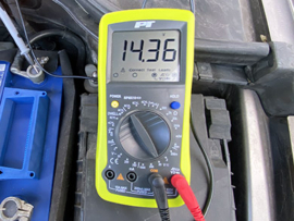
If a scanner is not available a multimeter can be used to carry out some basic yet vital testing:
- When evaluating a pick-up coil type sensor, the first test will be to check the sensor’s output voltage at engine cranking speed. With the meter set to read AC millivolts, the instrument should record about 200 millivolts when measured at the sensor’s fly lead – If the instrument reads zero, the sensor is faulty. For the exact reading it is best to check the manufacturer’s specifications.
- For a Hall-type sensor, the reference voltage (typically +5V) and the ground signal must be tested, although a thorough test would require an oscilloscope.
- Finally it is important to test the part for an open or short circuit. This is done by removing the sensor from the engine and then taking a reading by attaching one end of the multimeter to the reference voltage wire and the other to the earth: A reading of zero points to a short circuit, while infinite resistance means there is an open circuit – both of which indicate a faulty sensor.
If the crankshaft angle sensor fails any of the tests it will require replacement.
Replacing the CKP
Even though there are some crankshaft angle sensors that require special tools to re-program them, most can be replaced quite easily.
While sensor fitment and location will vary, depending on the type of vehicle, there are nevertheless some general guidelines that can be followed in most repairs:
- Before effecting any electrical repair it is always advisable to disconnect the battery earth terminal.
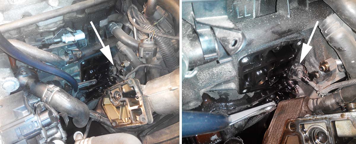
- After locating the sensor (The general position of which is described above) the fly lead can be disconnected.
- After removing the one, or in some cases, two bolts that secure the sensor it should be possible to free it from the engine assembly.
- Installation of the replacement part, will be in the reverse order of the removal sequence.
- Once installed, clear any fault code(s).
- Start the engine and make sure it starts and runs smoothly.
- Check that the engine warning light goes out.
Whereas fixing a car that won’t start or run properly is always a daunting prospect, following this guide will at least remove the crankshaft sensor from the list of suspects: Either by eliminating it as a possible cause, or enabling the DIY enthusiast to identify and replace the faulty part.
You may also be interested in: