In an age where engine performance and emissions are becoming increasingly important, it is vital for the efficient combustion of the fuel mix that the correct air to fuel ratios are maintained – across all engine loads, inlet manifold temperatures, and barometric pressures. For a spark-ignition engine, the stoichiometric mixture (the ideal air to fuel ratio to burn all the fuel with no excess air, also expressed as Lambda 1) is 14.7:1, equating to 14.7 grams of air for every gram of fuel.
To accurately regulate the air-fuel ratio, manufacturers typically rely on one of two sensor types to determine the ideal quantity of fuel to be injected into the combustion chamber or inlet manifold:
- MAP sensor (Manifold Air Pressure) that measures the absolute pressure inside the intake manifold to derive the airflow;
- MAF sensor (Mass Air Flow) that measures the volume of air being drawn into the engine.
Airflow, as measured by the MAF, tends to be more accurate than the calculated airflow derived from inlet manifold pressure – especially when combined with an oxygen sensor in a closed-loop engine management system.
Nevertheless, some systems incorporate both MAP and MAF, often relying on the MAP as a backup should the MAF fail.
Understanding MAF Sensors: How They Fail?
While a faulty MAF sensor is unlikely, in itself, to render a vehicle completely inoperative, it is nevertheless critical for the correct measurement of the fuel required by the engine. This makes it important to fully understand how the mass airflow sensor works, and what symptoms it displays when it fails.
How Does the Mass Air Flow Sensor Work?
The two most common designs of MAF sensors used to measure the airflow are:
- The vane meter. It is located ahead of the throttle, these older electro-mechanical devices, often found in systems such as Bosch’s L-Jetronic fuel injection, measure airflow by means of a spring-loaded mechanical flap. As these are rarely seen on modern motor cars it won’t be covered in this guide.
- Hotwire sensor. The most popular type determines airflow by either measuring the resistance across a heated wire or film:
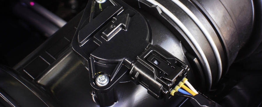
2.1. The “hot wire” sensor, commonly installed in the intake tube between the air filter and the throttle valve, has two sensing wires: One of which is heated by an electrical current.
2.2. The “heated film” sensor – usually located upstream of the throttle body relies on a hot film grid instead of individual wires.
Being a positive temperature coefficient (PTC) resistor, both devices work by having a constant voltage applied across the resistive film or wire. The positive temperature coefficient of the resistive wire means that as the temperature increases, so too does the resistance of the wire. With the MAF designed to function with the wire at a constant temperature, as more air passes across the wire, the current is increased to maintain the predefined temperature.
Thus the current, converted to a frequency or a voltage at the output of the sensor, is used by the engine control unit (ECU) to calculate the amount of fuel required.
In this system, ambient air temperature and humidity are automatically compensated for, as they also influence the temperature of the heated wire or film.
With an average of about 9,000 liters of air flowing through the sensitive MAF for every liter of fuel used, it is not uncommon for the sensor to become contaminated or even suffer an electrical failure.
How do Motorists are Beginning to Feel the Sensor is Faulty?
Similar to other functionally critical components in the modern car, a faulty MAF can be extremely difficult to diagnose – often exhibiting symptoms similar to inlet manifold leaks, low fuel pressure or even a faulty fuel pump.
It is therefore important that the most common symptoms of a defective or contaminated airflow sensor be clearly understood:

- As with most engine management components, the most obvious sign of a problem would be an engine check light coming on in the dashboard.
- Any problem with the MAF will invariably manifest in an inaccurate measurement of the air flowing into the engine, resulting in:
2.1. An engine displaying a rich mixture at idle, or running lean under load, could indicate a contaminated hot wire.
2.2. Without the correct airflow information, the ECU will be unable to accurately regulate the fuel supply to the engine, leading to a rough idle or even stalling and hard-starting.
2.3. Similarly an engine exhibiting signs of chronic over- or under-fueling could be suffering from a problematic MAF. These would manifest in poor throttle response, or in the discharge of plumes of black smoke from the exhaust outlet in an extremely rich mixture.
Should the vehicle exhibit any of these symptoms, indicating a problem with the MAF, the next step would be to perform a diagnostic evaluation of the system.
Your Starting Point for MAF Sensor Diagnosing and Repair
While any of the above symptoms MIGHT point to a defective MAF they could in fact be highlighting other problems; such as a leaking inlet manifold or faulty fuel pump or fuel pressure regulator. Therefore the sensor must be checked out objectively.
Visually checking for a problem with the mass airflow sensor. As mentioned above, the first sign of a faulty MAF is often the illumination of the engine warning light. In this case, the fault will be stored as a diagnostic trouble code (DTC) in the engine ECU and can be retrieved via the OBD (On-Board Diagnostic) port using a DTC scan tool.
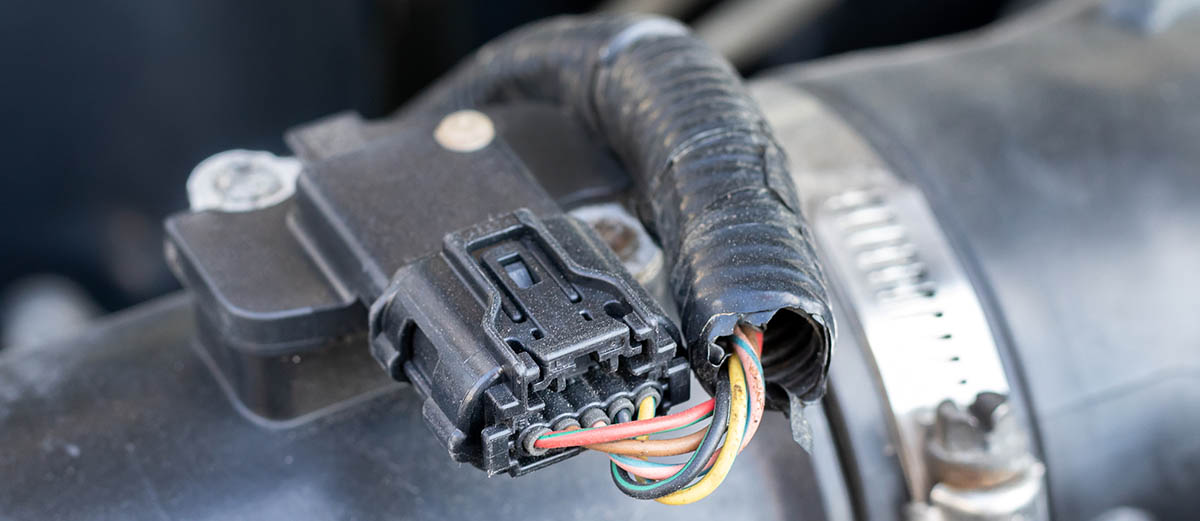
But before connecting the DTC tool it is advisable to visually inspect the system for signs of damage or cracks, and corroded or bent sensor terminals. It is also important to inspect the MAF sensor itself to make sure it isn’t contaminated with dirt and/ or oil.
Extracting the diagnostic trouble code stored in the ECU via the OBD port. If the system checks out visually then the next step would be to examine the DTCs which could include one of the following:
- P0100: MAF circuit malfunction
- P0101: MAF circuit range/performance
- P0102: MAF circuit low input
- P0103: MAF circuit high input
- P0104: MAF circuit intermittent
- P0171 system too lean (bank 1) – often caused by a faulty or contaminated MAF sensor
- P0174 system too lean (bank 2) – often caused by a faulty or contaminated MAF sensor
However, when interpreting a fault code that indicates a MAF sensor error it is important to take into account that these signals could be an indication that a different sensor, or another indirect problem, is the cause – including:
- A wiring harness problem on the MAF sensor circuit such as:
1.1. An intermittent or open circuit on the 12 volt supply from the battery to the MAF;
1.2. A faulty MAF earth connection.
1.3. An intermittent or open circuit on the output wire from the sensor;
1.4. Poor continuity across the MAF or computer connector terminals. - The ECU may be faulty.
To gain a more accurate diagnosis of the problem – either independently of the DTC, or as verification of the code – a more detailed examination might be necessary. This would require some form of electric/ electronic test equipment, such as a digital multimeter.
Checking the MAF sensor using a digital multimeter. The procedure for testing a hot-film MAF is basically the same as that for the hot-wire sensor, with the exception that instead of reading the voltage signal directly, for the hot-film sensor the frequency signal, in Hz, is measured.
Using the appropriate digital multimeter, the following tests will pinpoint a problem with the MAF – or give the sensor a clean bill of health:
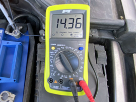
1. Check that the ECU is correctly powering the airflow meter and earthing the circuit:
• For this test the meter’s red probe should be attached to the connector power terminal and the meter’s black probe to an earth point;
• With the ignition key in the ON position, but without starting the engine, the meter should read between 10 and 13 volts.
2. Check that the MAF sensor element has continuity:
• This is done by testing the continuity of the sensor’s signal wire to earth at the MAF electrical connector, and can be accomplished by measuring the resistance of the circuit.
• A meter reading of approximately 0 Ohms should be recorded. If an infinite resistance is measured the MAF hot-film or wire is probably fused or broken and should be visually inspected.
3. Check the MAF sensor voltage signals:
• This test is conducted with the engine turning over at idle speed with the red probe connected to the same signal wire as above, and the black probe to earth – polarity is important;
• Depending on the sensor, a voltage reading of between 0.60 to 0.80V should be measured at idle. If the meter reads about 12V the probe has probably been incorrectly connected to the power wire, not the signal cable;
• Depending on the system, increasing the engine speed to between 2,500 and 3,500 RPM the voltage should increase to about 1.5 to 3.0 volts.
While most digital multimeters will be capable of performing the tests described above, on a hot-film MAF it may be necessary to check the sensor with the aid of a scope to accurately capture the output frequencies.
Checking a hot-film MAF sensor’s frequency output using a scope. With the hot-film air flow sensor the output signal is measured as a frequency that changes relative to the amount of air flowing through the sensor: A low frequency depicts a small air flow, while a high frequency indicates an increase in air flow.
While actual signal readings may vary across different types of ECUs and mass air flow sensors, signals are generally measured over a specific cycle with the engine at operating temperature: Ignition on, cranking, idle, 2000 RPM, 3000 RPM and back to idle again.
During these tests the following signal deviations may indicate a possible MAF sensor fault:
• No signal – This is usually as a result of the probes not having a good connection, poor or no power supply to the sensor, or a faulty sensorl;
• A high signal voltage – Indicates a poor or absent earth connection on the power supply, or a non-functional sensor;
• A corrupted signal – Stems from a damaged signal wire or power supply harness, poor continuity across the connector terminals, or a breakdown of the MAF;
• Excessive signal offset – Commonly points to a weak power supply to the sensor, air bleeding into the air intake system, or a malfunction of the sensor.
Having established that the MAF sensor is faulty through the appropriate diagnosis the unit will need to be replaced.
Safely replacing the MAF sensor. Before setting out to replace the MAF it is important to remember that the sensor is a very sensitive electronic device and should be handled with the utmost care during the installation. Never touch the electronics as this could damage the unit. To check the price for a new MAF sensor you can follow this link.
A Short List of Steps for Replacing the Mass Airflow Sensor
The replacement consists of three simple steps:
- Removing the faulty unit:
1.1. Start by disconnecting the sensor’s electrical connector-block.
1.2. Remove the MAF unit.
1.3. If the sensor has a vacuum pipe, loosen the clamps that attach the body to the air intake duct and remove the sensor.
2. Refitting the replacement unit:
2.1. Carefully fit the replacement unit into the air intake tube and reconnect the MAF connector. If fitted with a suction pipe, retighten all the clamps.
2.2. Inspect the induction system for potential leaks, making sure that any O-rings are not damaged or distorted.
3. Reset the system and confirm the efficacy of the repair:
3.1. Using a diagnostic tool, delete any fault code(s).
3.2. Check that the check-engine light is extinguished.
3.3. Start the engine, and check for any new fault codes.
3.4. Road-test the car.
To ensure an effective and durable repair it is important that the diagnosis and replacement of the air flow sensor are conducted meticulously and with great care If done correctly the vehicle will have been returned to perfect working order, with several tangible benefits, including: Improved fuel consumption, drivability and performance.


Leave A Comment